Figure 3.12 Two dial indicators are used to determine the relative position of the movable shaft with respect to the stationary shaft.

Figure 3.13 The rim dial is used to measure offset in one plane along the shaft lengths.

Figure 3.14 The face dial measures angularity or slope between the shafts.

Figure 3.15 Uncoupled shafts.

Figure 3.16 Coupled shafts, rim dial.

Figure 3.17 Coupled shafts, face dial

Figure 3.18 Mounting fixtures

Figure 3.20 Documenting as found readings.

Figure 3.21 Measuring vertical misalignment, 6 o’clock.

Figure 3.22 Setting the sag value

Figure 3.23 Measuring vertical misalignment, 12 o’clock.

Figure 3.24 Example, TIR readings.


Figure 3.25 Measuring horizontal misalignment

Figure 3.26 Measuring horizontal misalignment, 9 o’clock

Figure 3.27 Measuring horizontal misalignment, 3 o’clock.

Figure 3.28 Example, horizontal TIR readings.


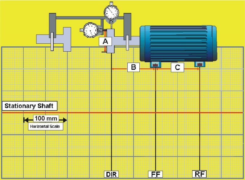
Figure 3.29 Set up and dimensions

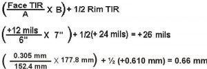
Figure 3.30 Equation, front feet calculation

Figure 3.31 Equation, rear feet calculation

Figure 3.32 Front feet calculation. The front feet are 26 mils (0.66 mm) too high; shims need to be removed.

Figure 3.33 Rear feet calculation. The rear feet are 74.0 mils (1.88 mm) too high; shims need to be removed.

Figure 3.34 Setting up the graph.

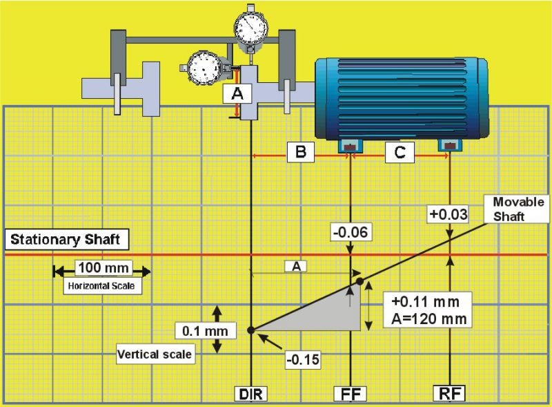
Figure 3.35 Plotting

Figure 3.36 Graph, feet positions.

Figure 3.37 Making vertical corrections

Figure 3.38 Horizontal corrections. Dial indicator at the feet.

Figure 3.39 Horizontal corrections. Monitoring dial indicators mounted at the coupling.


