Machine train alignment isn’t where you start if you’re new to shaft alignment. It’s a more advanced application—best tackled once you’re confident and consistent with aligning standard two-element drive systems. With those fundamentals in place, you’ll be better equipped to handle the added complexity of multi-element systems.
Because of that complexity, successful train alignment depends on solid preparation, disciplined execution, and thorough post-alignment verification. The following best practices will help guide you through every phase of the process—before, during, and after the job.
Before the alignment: plan with precision
Before a single bolt is loosened, success starts with preparation. The more you understand your system and its physical limits, the fewer surprises you’ll encounter once the laser alignment tool comes out. Careful planning is what separates a smooth alignment from a long, frustrating day in the field.
Understand your system
A machine train is any setup with multiple couplings, such as:
- Motor–gearbox–pump
- Motor–gearbox–compressor
- Motor-gearbox-ballmill
- Motor-gearbox-mill stands and more…
These systems may be straight-line, right-angle, or even zigzag in configuration. Each rotating element must ultimately share a common centreline of rotation with its counterpart.
Because these assets are often high-value and critical to production, understanding your system’s configuration and how it behaves under load is essential before making any moves.
Pre-alignment
Before beginning your precision alignment, a methodical pre-alignment process must be followed to ensure the machine train is mechanically sound. This phase involves several critical steps:
- Step 1: Rough Alignment (If machines are easily movable)
- Step 2: Eliminating Obvious Soft Foot
- Step 3: Initial Bolt Tightening
- Step 4: Final Soft Foot Correction
Beyond these sequenced steps, a number of additional preparatory checks are highly recommended, including:
- Thoroughly cleaning the machine feet and base
- Consolidating all shim packs
- Checking the shafts for run-out if rotatable
- Inspecting for excessive pipe strain
Completing this preparation ensures a solid foundation and prevents the most common causes of alignment failure. For more information on pre-alignment, check out our How to Perform Pre-Alignment Video, which outlines each step in detail.
Define movement boundaries and alignment targets
Every machine has physical limits—edges of baseplates, bolt hole clearances, and shim capacity. Before beginning:
- Identify shim change limits
- Check side-to-side and up-down movement ranges
- Note any bolt or baseplate restrictions
- Ensure OEM alignment targets or thermal growth specifications are known and correctly applied.
Defining your movement envelope upfront prevents wasted effort and avoids costly modifications, like grinding baseplates or re-boring holes later.
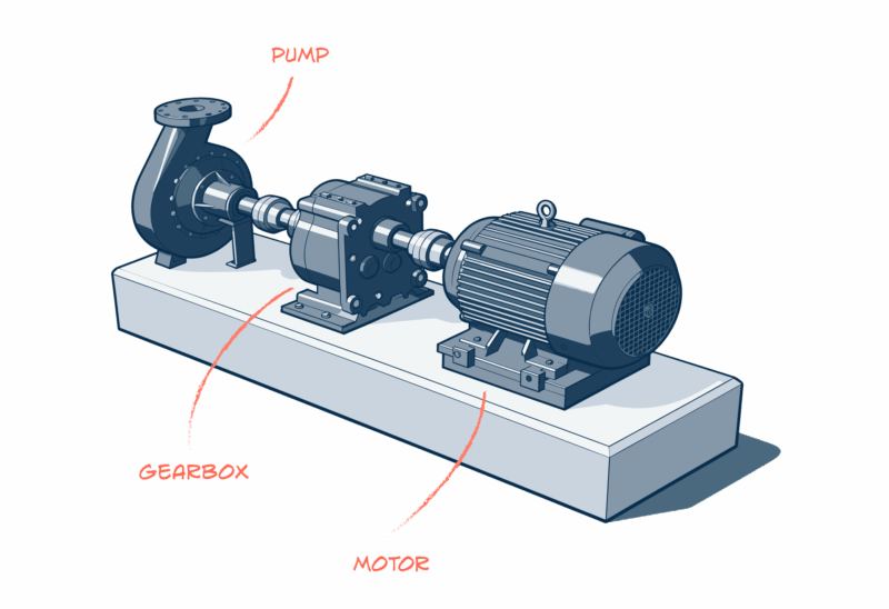
Graph the machine train
Before starting, it is crucial to establish a visual plan of your machine train. While a simple sketch on paper (graph paper was traditionally used) can still be helpful for quick visualisation, the entire process of graphing and calculating movements is now typically performed within the alignment program of your laser shaft alignment tool in the machine setup function.
The graph, whether a sketch or in the alignment software, serves to:
- Clearly show the initial misalignment.
- Logically plan machine movements to minimise corrections.
- Aid in communicating the alignment strategy to your team.
- Provide a record of both the “as-found” and “as-left” states.
Using the tool’s machine setup function and inputting key data—such as dimensions, coupling types, RPM, movement boundaries, and thermal growth influences—ensures the highest level of accuracy and efficiency for this complex job.
During the alignment: align with process, not panic
Once the planning is complete, it’s time to execute—slowly, methodically, and with discipline. Every adjustment affects the next, so this phase is all about control and consistency. Following a structured process ensures accuracy and makes it so that you don’t lose track of your place.
Identify every shaft centreline
The golden rule of machine train alignment is do not move anything until you know where everything is. Use your laser alignment tool to locate and record the precise centerline of rotation for each shaft.

We recommend using a dedicated Machine Train programme with your laser alignment tool to do this type of job. For example, Acoem’s AT-400, AT-300, RT-300, and EXO are all solutions that work with our dedicated Machine Train application.
Once all positions are captured, your tool will determine how each must shift—vertically or horizontally—to form a continuous centerline across the entire train.
Designating a stationary reference
In a machine train, one machine must be designated as the stationary reference, which serves as the fixed point for all alignment calculations. While a traditional approach is to choose the machine that is the hardest to move (often locked in by anchor bolts or piping), modern laser alignment tools offer more efficient methods:
- Minimum Moves Function: This common function within alignment software automatically selects the reference machine that requires the smallest overall adjustments from the other machines. The calculation prioritises minimising horizontal movements and the need to remove shims.
- Manual Selection: You always retain the option to manually set any specific machine in the train as the stationary reference, which is often necessary to account for real-world constraints like base-bound or bolt-bound conditions.
Simulate the move
You can use a built-in Shim Simulator to digitally simulate the required machine moves before physically adjusting heavy equipment that often requires cranes or multiple people. This crucial step allows you to determine the precise amount of shims needed for the adjustment and confirms you have the correct shims readily available.
Verify every correction
Be meticulous with your approach to making adjustments to your machines. Re-measure when adjustments are made to ensure that you are on the right track. Be sure to torque the bolts evenly in a cross pattern, ideally using a torque wrench to ensure controlled and consistent tension.
This is where patience pays off—small, measured corrections yield lasting results. Rushing through this phase often leads to starting over. Ensure you are within the selected alignment tolerance when the job is finished.
After the alignment: verify, record, reflect
Finishing the alignment isn’t the end—it’s the start of validation. Proper documentation and post-alignment checks confirm that your hard work will hold under real operating conditions. Taking the time to review results and record data turns a good alignment into a reliable one.
Document everything
Record your “as-found” and “as-left” measurements, save alignment graphs, and note any lessons learned. These records not only provide traceability but also serve as valuable references for future alignments or troubleshooting.
Operate and observe
A machine train isn’t truly aligned until it proves itself in operation. Let it run for at least 100 hours while monitoring:
- Smooth coupling behavior
- Stable vibration and temperature readings
- Absence of abnormal wear or stress
If all conditions remain steady, you’ve successfully completed the job.
Final thoughts
Machine train alignments can vary in complexity depending on how many components are involved. When scheduling, always allow more time than you think you’ll need—precision takes patience. By working methodically, observing how each element interacts, and remembering that you’re aligning one complete system—not individual machines—you’ll achieve better results with less frustration and fewer mistakes.
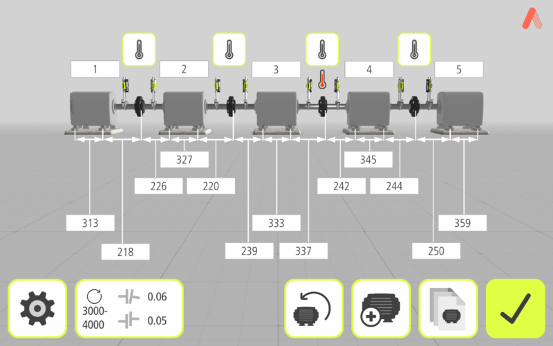
Acoem’s machine train application
Acoem’s dedicated Machine Train application simplifies the alignment of systems with more than two rotating machines. Available for the AT-400, AT-300/RT-300, and EXO, the app provides a clear, 3D overview of each machine’s position within the train and identifies which should serve as the stationary reference—helping you minimise unnecessary adjustments and save valuable time.
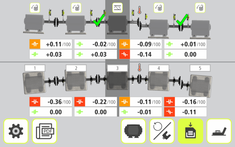
Users can lock any machine to account for bolt- or base-bound restrictions, set target values, and visualise alignment progress in real time.
The result is a faster, more intuitive alignment process that improves accuracy and takes the stress out of complex multi-machine jobs.
Get in touch with our experts to learn more.