


As stated in those blogs the coupling manufacture’s tolerances are for the coupling. As maintenance professionals we are concerned with the coupling, however we are more concerned with the bearings in the machines. Precision shaft alignment tolerances are used to protect the bearings, seals, etc. Of course the coupling will last much longer as well.
During a recent Acoem RT-300 training class the differences of coupling alignment tolerances vs. precision shaft alignment tolerances were very apparent. The alignment of an 1800 RPM electric motor and centrifugal pump with a model 1070T grid coupling was checked. This was a fairly new installation with the initial alignment performed by the installation contractor.
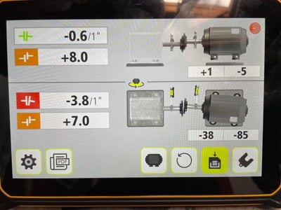
The “as found” alignment results showed the vertical angle to be within tolerance however the horizontal angular misalignment was more than 5 times tolerance. The vertical & horizontal offset misalignment was within 2X tolerance. Green coupling icons = in tolerance, orange = within 2X tolerance, & red = more then 2X tolerance.
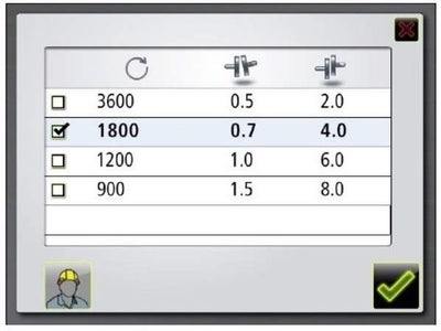
Acceptable precision shaft alignment tolerances for 1800 RPM are 0.7mils/1” angular and 4.0 mils offset.
The coupling manufacture’s alignment tolerances for the 1070T grid coupling (installation limits) are from the installation and maintenance instructions found on the manufacture’s website.
The “Angular Misalignment” value is the maximum difference between the measurements X and Y taken at opposite ends of the hub flanges, as shown in Figure 5
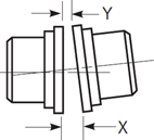
Table 4 – Maximum angular misalignment value
| Angular | Size | 1020T | 1030T | 1040T | 1050T | 1060T | 1070T | 1080T | 1090T |
| X-Y | Inch | 0.003 | 0.003 | 0.003 | 0.004 | 0.005 | 0.005 | 0.006 | 0.007 |
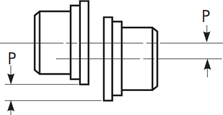
Table 5 – Maximum difference P
| Parallel Offset | Size | 1020T | 1030T | 1040T | 1050T | 1060T | 1070T | 1080T | 1090T |
| P | Inch | 0.006 | 0.006 | 0.006 | 0.008 | 0.008 | 0.008 | 0.008 | 0.008 |
Table 4 lists the “Maximum angular misalignment value” as a gap difference of 0.005” (5 mils) top to bottom and side to side measured at the O.D. of the coupling hubs which is 4”. Table 5 lists the “Maximum difference” for the parallel (offset) misalignment as 0.008” (8 mils).
Further down in the instructions were the “Operation limits” for the 1070T coupling. The “Angular Operation Limits” is a 0.020” (20 mils) gap difference with the “Parallel Operation limits” of 0.016” (16 mils).
To clarify the angular alignment values, the coupling manufacture lists the angular misalignment as a gap difference between the coupling faces (face reading) whereas Acoem Fixturlaser alignment systems display angular alignment as a slope which is displayed as mils per 1” (mils/1”). To convert gap to slope, the gap difference is divided by the coupling diameter to get mils per 1” (mils/1”).
The as found offset (parallel) values of +8.0 mils vertical & +7.0 mils horizontal are within the 8.0 mils (0.008”) allowed by the coupling tolerances but are more than the 4.0 mils acceptable shaft alignment tolerance. Even though they “are close” this offset misalignment at the coupling creates radial force which is exerted to shafts reducing bearing and seal life.
The -3.8mils/1” as found horizontal angular misalignment is 5.4 times the allowed shaft alignment tolerance of 0.7mils/1”. 3.8mils/1” is the same as a 15.2 mil gap at the coupling hub O.D. (3.8mils x 4” coupling hub diameter). That amount of angular misalignment transmits a tremendous axial force from the coupling to the shafts.
This 15.2 mil gap (0.0152”) is three times the allowed coupling tolerance installation limit of 5.0 mils (0.005”) however it is within the 20.0 mil (0.020”) Angular Operation limit. An equipment installer not versed in precision shaft alignment tolerances could interpret this as “while the alignment is not great it is within operational limits for the coupling so we’re good!” Which is not the case for this alignment.
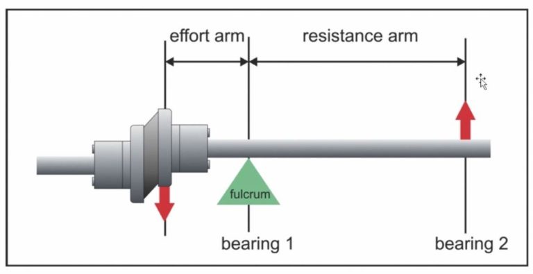
The goal of precision shaft alignment is to minimize force at the coupling which is in turn transmitted to the shafts, bearings, seals, & etc. Aligning to coupling values does not minimize this force. Excess force reduces bearing life as shown in the L10 bearing life formula.
To borrow from a popular Syfy movie series set in a galaxy far, far way, “The Force” there is a good thing. When making precision shaft alignments here on Earth “force” is a bad thing!
- Couplings
- Reduce Force to Maximize L10 Bearing Life


