


Collecting a correct time waveform
Time waveform in vibration measurement technology is basically known as “raw signal” as it represents a real information from the machine about forces being generated. As a first step of measurement, all vibration analyzer captures time wave form and then process it to bring various characteristic value. So the time waveform is a very important parameter of the technology.
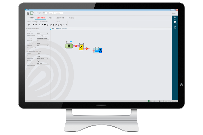
Using automatic tools such as the NESTi4.0 software setup module can help the user to make sure that the setting of this raw data is correct just based on the machine description, and such guarantee a reliable monitoring.
In case you go for a manual setup, a perfect setting of time waveform can be ensured by following some elementary guidelines. As a basic rule, time waveform is function of:
- sampling frequency: how fast do i capture data?
- and the number of samples: how much data should i capture?
These inputs corresponds to the information commonly asked in vibration analysis software for the setup of the time waveform. But the real question is what information do I need to define these parameters properly? With bad settings, one could witness a normal time signal whereas the machine is experiencing some trouble. So here are few things you need to know to make sure your monitoring strategy will be efficient.
Sampling Frequency
Technically, sampling frequency is the frequency at which the data collector samples the real analog signal in to digital signal. As per Nyquist Theorem, sampling frequency must be greater than or equal to 2.56 times the maximum frequency of interest. So again we have a question, what should be Fmax for a time waveform? Your goal of measurement will help you to answer this question.
Different types of faults will typically be characterized in different frequency ranges. to make it short, your Fmax will have to be suitable to the type of faults you are looking for. Here is an illustration to explain the concept.
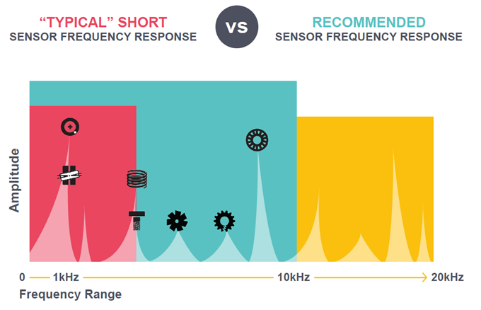
Generally speaking, you of course also want to monitor your machine bearings. To capture bearing signals at initial stage of defect, sampling frequency must be very high as this defect will generate vibration at high frequency. For a large size bearing rotating at slow speed, defect frequency may be in range of higher than 15 kHz. To cover most common application efficiently at the scale of an industrial plant, we recommend you to make sure that your vibration analyzer can analyze up to 20kHz of Fmax, which means a sampling frequency 51.2 kHz. It is for example the case of the FALCON that can also go up to 80 kHz of Fmax if needed in the Ultimate version…Do not underestimate the importance of the sampling frequency. If it is set too low, you may miss many useful information of high frequency range and not be able to establish the right diagnostic
Number of samples
The duration of the time waveform measurement is a direct result of the sampling rate (how fast) and the number of samples (how much). At a given sampling rate, the length of the time waveform will be longer with a higher number of samples, and shorter with a smaller number of samples.
For the best fault detection capabilities, you need to make sure that a minimum 7 to 10 shaft rotations are covered in the time waveform (for a steady operating condition). So now we have three parameters to take care:
- The sampling Frequency, impacting the frequency content available in the signal measured
- The length of time waveform, impacting the fault detection capabilities
- And the number of samples, commonly asked in vibration analysis software for the time waveform setup
The correct process is to:
- Start with estimation of expected Fmax frequency based of highest targeted frequency,
- Fix the sampling frequency accordingly (= Fmax x 2.56).
- Based on the shaft rotation speed, calculate the time required to capture 10 revolutions of the shaft
-
- And from this – the number of samples needed can be calculated by formula:
Ns = Fs x Ts
Where Ns = Number of samples
Fs = Sampling frequency in Hz or CPS
Ts = Time (duration) of the waveform in Sec
NB: It is to be ensured that the condition monitoring package (Combination of hardware and software) are capable to offer you above customization.


