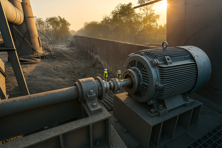
















Every plant has a shortlist. Most unfavourite machines — that nobody wants to align.
The turbine coupling where the reading keeps drifting no matter how careful the technician is. The cement mill spacer shaft where you can’t even get a wrench access from the side, let alone rotate it there. The high-speed turbine where the oil film makes finding the true centre feel like a guessing game. The old locomotive alternator where alignment has always meant dials, patience, and a fair bit of guesswork.
These aren’t rare edge cases. They’re the machines every reliability team quietly works around — checked less often, trusted less, and often left “close enough” because getting them properly aligned takes more time. It’s exhausting, it causes extended downtime, and it’s usually the reason your team is stuck at the plant long after their shift was supposed to end.
The reason isn’t the technician. It’s the method.
Why the standard approach breaks down here
Most shaft alignment —method — depends on the same basic idea: rotate the shaft to a few fixed positions, take a clean reading at each position, and calculate. It works well for the vast majority of machines. But it assumes two things that not every shaft can give you.

It assumes the shaft settles quickly.
On high-speed turbines and compressors running on sleeve bearings, the shaft rides on a film of oil. Move it to a position, and it doesn’t stop instantly — it keeps drifting on that film for a few seconds before settling. Take the reading too soon, and three fixed points won’t tell you the truth about where the shaft actually sits.
It assumes the shaft can rotate freely to those points.
Non-rotatable shafts, awkward couplings, and machines where the coupling can’t be turned to a specific clock position simply can’t give you a clean 3-point read. Neither can heavily corroded or pitted shaft surfaces, where surface distortion throws off single-point accuracy.
Force the standard method onto these machines and you get one of two outcomes: an alignment job that takes far longer than it should, or a result nobody fully trusts.

What if the tool adapted to the machine?
When machinery is complex, standard alignment methods simply do not capture enough information to give you a true picture.
To get accurate results on unstable machinery, you need more data. This is exactly why Dual Multipoint was developed as a new measurement choice for the Acoem AT-300 and AT-400 systems. Instead of forcing three readings at fixed positions, it lets you start measuring from wherever the shaft happens to sit, and takes readings across 6 to 9 rotational positions instead of three. More data points, spread around the full rotation, means the calculation isn’t riding on the accuracy of just three moments — it’s built from a much larger picture of how the shaft actually moves.
That single change quietly removes the constraints that made certain machines so difficult:
- No forced positioning. You measure the shaft where it is, not where the method demands it should be.
- Built for oil-film settling. On turbines and sliding-bearing machinery, extra points across the rotation absorb the noise that a rushed 3-point read can’t.
- Handles non-rotatable shafts. Using a chain fixture with wider contact points, the axis of rotation can be simulated by the fixture across the shaft — bringing multipoint accuracy to shafts that can’t be turned at all.
- More reliable on rough or distorted surfaces. Additional readings spread around the shaft dilute the effect of any single bad data point from surface pitting or corrosion.

Making the complex simple
At the end of the day, reliability isn’t just about keeping the machines running; it’s about keeping your maintenance routines predictable, safe, and stress-free.
You shouldn’t have to fight your equipment to align it. By upgrading to a system designed specifically for these worst-case scenarios, your team can achieve precision faster, reduce wear on critical assets, and — most importantly — get the job done right the first time.