Twin Laser Alignment Method

Alignment Knowledge: All you ever wanted to know about shaft alignment.

Coning

As mentioned in the first sections, shaft alignment is all about making two rotating shafts co-linear. To achieve this, different kinds of methods are used to determine the axis of rotation of one unit and compare it to another one. When using the twin laser method a special method is used called “coning” to project the axis of rotation. The fact that light from the laser creates a perfectly straight line with no sag makes it possible to project the axis of rotation of any rotating object even over long distances. By attaching a laser to the rotating object, the laser beam will describe a cone. When the “cone” is projected in one plane the beam will describe a circle and it’s center is the center of rotation in that particular plane. The direction of the axis of rotation is determined by projecting the center of rotation in two planes.

Figure 3.71 Coning principle 1. The center of the circle is the rotational center of the shaft.

By adjusting the angle of the out coming laser beam on the transmitter, the diameter of the projected circle decreases until the beam eventually creates a spot. The coning technique can be used to create “points” at different distances from the rotational object to project the axis of rotation.

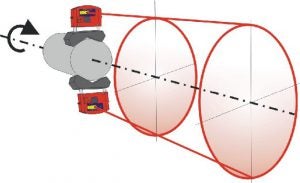
Figure 3.72 Coning principle 2. The axis of rotation is made into a single point at a distance from the shaft end.

Comparison to dial indicator method

By using the coning technique (principle 1) the twin laser based alignment instruments basically uses the same method as alignment with dial indicators. In fact, the reversed dial indicator method uses exactly the same principle to determine the position of an rotating axis by defining the offset in two planes. While a dial indicator measures the offset by needle and plunger the laser transmitter/detector (TD) unit measures the offset by detecting the movement of a laser beam on a single axis detector. Below we describe the relationship between the reversed dial method and the method used with twin lasers.

The pictures (3.73 & 3.74) compares the two methods when measuring the offset in the plane of the stationary side of the coupling DIS or TD-S:

The pictures are exaggerated to show the principle of how readings are taken.

In the example we can see that the rotational centre of the movable shaft is +2.5 above the stationary shaft. The offset is +2.5 in the plane of the stationary coupling (DIS / TD-S)

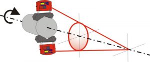
Figure 3.73 Reverse-Rim dial indicator method. Measurement of stationary side offset, DIS.
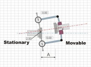
Figure 3.74 Twin laser method. Measurement of stationary side offset, TD-S

In a twin laser system the same type of measurement is simultaneously measured in the second plane . Sign changes isn’t necessary as the plus/minus direction is reversed in the TD-M unit. In the pictures below the distance (offset) between both axis of rotation in the second plane is +4,80

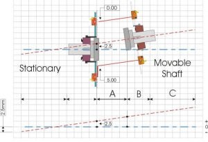
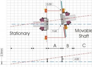
Figure 3.75 Reverse-Rim method. Measurement of movable side offset, DIM
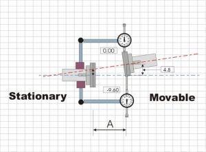
Figure 3.76 Twin laser method. Measurement of movable side offset, TD-M.

When having the two offset values in two planes it is now possible to determine the position of the axis of rotation for the movable machine. By adding the values for distance B and C and we can use the same calculation which is used in the Reversed-Dial indicator method to determine the feet correction values. In laser alignment these calculations are made quickly and continuously in the display unit making it possible to update adjustments to the machine while they are being made.

(real time)Figure 3.77 Equations
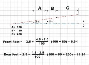
Figure 3.78 Example, feet calculation.
!
by Acoem contributor | September 6, 2022
Share :

View our resources

Visit our library of educational videos, podcasts and more.

View more

Suscribe to the blog

Ici formulaire à venir

Would you like to…?