Dial Indicator Alignment Basics

Dial indicators are measuring devices designed expressly to measure relative position. The primary parts of a dial indicator are the face or dial, the case, and the plunger. The plunger is a spring loaded part that can be depressed into the case causing the dial to move clockwise.

Dial Indicator Alignment basic 1

Figure 3.1 The dial indicator

The plunger is fully extended out of the case if no pressure is applied to it. The total travel (all the way out to all the way in) varies depending on the particular indicator model. For shaft alignment, we typi­cally use dial indicators with 0.250″ – 0.300” total travel.

The plunger moves a needle clockwise when pushed in and counter clockwise when let out. The face can be rotated so that the needle points to zero. The case is held by a clamp and holding rod which are, in turn, held by a jig or magnetic base. The number of set up options are too numerous for this discussion. The two types of face design are balanced and continuous.

Dial indicator signs

With the plunger set to approximately mid-position, the face dial is set to read zero.

Dial Indicator Signs 1


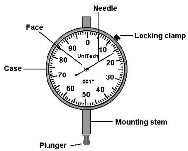
Figure 3.2 Dial indicator signs

From this zero reference point, two rules apply:

  • As the plunger moves out of the case, the needle travels counter-clockwise…giving a NEGATIVE reading.
  • As the plunger moves into the case, the needle travels clockwise…giving a POSITIVE reading.

Dial Indicator Signs 2 Dial Indicator Signs 3

Figure 3.3 Positive readings when the plunger moves into the case, negative when the plunger moves out.

Bar sag

The dial indicator bar sag describes a bending of the hardware used to support a dial indicator or other part which spans the coupling. The bending action occurs as a result of gravity and cannot be totally eliminated in almost all cases of alignment. Numerous attempts have been made by fixture manufacturers to minimize the amount of sag that occurs; however, none have been successful in “eliminating” it for all alignment situations, only in minimizing it.

Factors that influence how much sag exists include:

  • Weight of the dial indicator and other parts that are overhung.
  • Height of the supporting fixture required to clear the coupling
  • Span of the indicator bar(s)
  • Stiffness of the fixture hardware materials
  • Specific geometry of the hardware arrangement.

In all cases of alignment, efforts should be made to minimize the amount of sag present. If it is not kept to a minimum, it is often not repeatable and, therefore, introduces different amounts of error. As long as the amount of bar sag is known and is consistent, it can be compensated for during the alignment process.

Quantifying the sag

During each alignment task, after the indicator(s) have been set up on the machine, it is necessary to determine how much bar sag exists. To determine the amount of sag, the fixtures must be taken off the machine and remounted on a rigid mandrel, such as a piece of steel pipe. It is important to note that indicator bar sag cannot be determined from a reading taken by rotating the shafts. The reason is that as the fixtures are rotated from 12:00 to 6:00 while mounted on the machine, the reading given includes a combination of sag and misalignment.

To determine sag, perform the steps below:

  1. Mount the fixtures on the machine as they will be mounted during the alignment task. Verify fixture tightness, repeatability, etc.
  2. Dismount fixtures from the machine shafts and remount on a rigid mandrel.
  3. Position the indicator plunger(s) at the 12:00 position and set the dial(s) to zero.

Determining the Amount of Sag 1

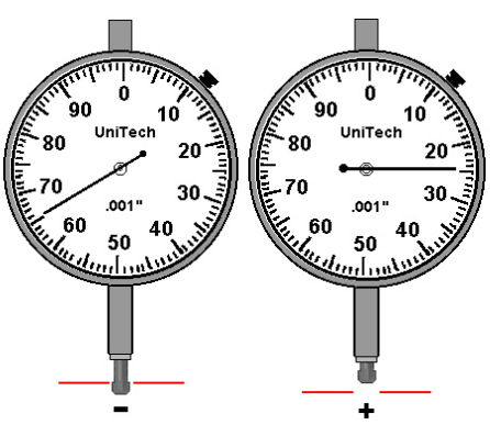
Figure 3.4 Determining bar sag, zero at 12 o’clock.

4. Rotate the fixtures to the 6:00 position and read the amount of sag.

Determining the Amount of Sag 2

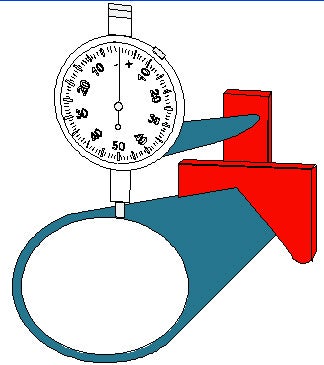
Figure 3.5 Determining bar sag, reading at 6 o’clock.

Correcting for sag

Once the amount of sag is determined, you must properly eliminate its adverse effects on all vertical offset readings. The simplest way to eliminate the effects of sag is to dial it into the readings at the initial measurement position.

  • For readings where the dial is normally zeroed at 12:00 and rotated to 6:00, set the dial to the positive value of sag at the 12:00 position.
  • For readings where the dial is normally zeroed at 6:00 and rotated to 12:00, set the dial to the negative value of sag at the 6:00 position.

Once sag is “dialed in” as described above, all TIR values are correct; no further sag compensation means are required.

Measuring offset using dial indicators

To measure offset using dial indicators, a fixture bracket is attached to one shaft and the dial is setup to contact the other shaft. The dial is set to zero at position #1, for example 12:00.

Measuring Offset Using Dial Indicators 1

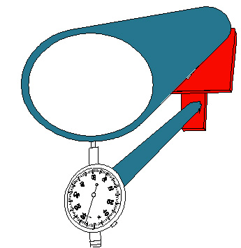
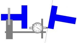
Figure 3.6 Measuring offset, position #1.

The dial is then rotated 180 degrees, for example, to the 6:00 position.

Measuring Offset Using Dial Indicators 2

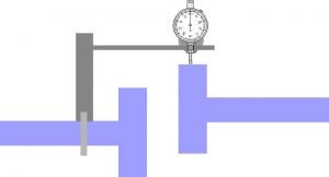
Figure 3.7 Measuring offset, position #2.

When shaft offset readings are obtained in this manner, the total indicator reading (TIR) is twice the amount of offset. You must divide offset TIR by 2 to determine offset. Referring to the illustration below, notice that the offset between the two shafts is 0.020” (0.508 mm), but the TIR is 0.040” (1.016 mm).

Measuring Offset Using Dial Indicators 3

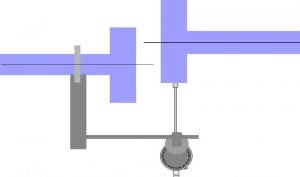
Figure 5.8 The offset is half the TIR (Total Indicator Reading).

Measuring Angularity With Face Dial Indicators

To measure angularity using dial indicators, a fixture bracket is attached to one shaft and the dial is set-up to contact the face of the other coupling hub. The dial is set to zero at position #1, for example, 12:00.

Measuring Angularity With Face Dial Indicators 1

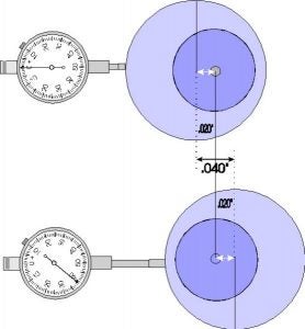
Figure 3.9 Measuring angularity, position #1.

The dial is then rotated 180 degrees, for example, to the 6:00 position.

Measuring Angularity With Face Dial Indicators 2

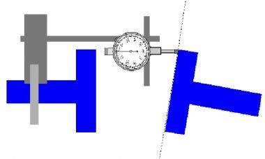
Figure 3.10 Measuring angularity, position #2.

When shaft angularity readings are obtained in this manner, the amount of angularity equals the total indicator reading (TIR) divided by the indicator circle diameter. For example, if the 6:00 TIR is +0.010” (0.254 mm) and the indicator circle diameter is 5” (127 mm), the amount of angularity is +0.002”/” (0.002 mm/mm).

!
by Acoem contributor | September 6, 2022
Share :

View our resources

Visit our library of educational videos, podcasts and more.

View more

Suscribe to the blog

Ici formulaire à venir

Would you like to…?