


Unique label
First, it is important to place a unique label on each machine. It is also important to record the location of the machine within the plant. If the machine has a unique identifier you can record this in the Machine ID field on the Machine Data Sheet.
The machine number is used to order the number of machines in a route. Critical can be checked if the machine requires planned downtime for repairs or to set priority on a route.
Speed reference location is not required, but is helpful in the case of multiple gearboxes or other configurations. The numbers 1 and 2 denote the motor, while 3 and 4 denote the coupling or gearbox input, and so on.
Motor
Additionally, each machine must have a motor. You will need to specify whether the bearings are journal or rolling element because each type produces different types of vibration.
In addition to bearings, the mounting type needs to be identified. If the motor is on a flexible mount, alarm levels are increased because vibration can occur at a higher amplitude.
Power can either be set to horsepower or to K-W. Note that output speed on a fixed speed motor will not necessarily correspond to the speed on the machine’s nameplate. It’s important to determine the actual rotations per minute (rpm) with a stroboscope or a similar tool. With variable speed motors it’s likely that the speed will change each time data is collected.
Some other important info to record:
- Orientation is where you can record what direction the machine is facing.
- Input either flexible or rigid in the transmission section.
- Belt ratio can be calculated by dividing the driven speed by the driver speed.
For gearboxes, each stage is two meshing gears. For example, if there are three shafts, then there are two stages. The number of stages can be entered in the “Gearbox” section. If known, the number of teeth in a gear can be entered as well.
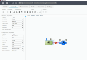
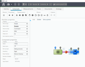
Next, the bearing type, mounting type, and the type of machine can be entered in the “Driven” section. An example would be “Roller Bearing,” “Rigid,” and “Pump.”
Example
Here is an example of a report of saved data from our SMC:
.
Although this may seem like a lot of information to record, the whole process actually goes quite quickly on the job. And once you use the Machine Data Sheet a few times, it will become second nature.
Once you have collected and recorded all the pertinent information, you can begin the process of data collection and analysis.