Rim and Face method overview

The Rim-Face method is recognized as the oldest method of shaft alignment. Many different variations of the rim-face method are used, including straight edge and feeler gauge methods, single dial rim-face, two dial rim-face, trial and error rim-face, etc. In this training, we will focus on two dial rim-face alignment and how to accurately determine shaft positions using calculation and graphing procedures.

Rim and Face method overview

Figure 3.12 Two dial indicators are used to determine the relative position of the movable shaft with respect to the stationary shaft.
Figure 3.13 The rim dial is used to measure offset in one plane along the shaft lengths.
Figure 3.14 The face dial measures angularity or slope between the shafts.

Using the offset and angularity measurements along with fixture setup and machine dimensions, the relative position of the movable shaft is determined by performing calculations or by graphing/plotting.

Fixturing Overview

A variety of shaft alignment fixtures are available for performing Rim-Face alignment. Selection and use of a commercial package designed to accommodate a variety of shaft diameters is recommended. The fixtures should include an assortment of rods to span various coupling lengths. These packages expedite the precision alignment process. Also, sag values can be pre-determined for the standard rod assortment.

For machines with sufficient space between coupling halves, fixtures can be mounted such that the dial indicators are in direct contact with the coupling or the shaft. In this case, the alignment can be performed with the shafts un-coupled.

Figure 3.15 Uncoupled shafts.

When machines are close-coupled, there is generally NOT sufficient room to mount indicators to contact the coupling hub. In these cases, rim-face alignment can be performed with the shafts coupled. Indicators are often mounted to contact a bracket, similar to the illustration below.

Figure 3.16 Coupled shafts, rim dial.
Figure 3.17 Coupled shafts, face dial

Mounting

Fixture mounting procedures are obviously dependent on the specific type of hardware being used. For this training, you will perform the alignment with the shafts un-coupled and the indicators mounted in direct contact with the rim and face of the movable shaft’s coupling.

To mount the fixtures follow these steps:

1. With the coupling broken, mount a fixture bracket to the stationary shaft or coupling hub as illustrated below.

Figure 3.18 Mounting fixtures

2. Span the coupling from the mounted bracket with an indicator support rod.

3. Rotate the fixture to 12:00.

4. Attach a face dial indicator with the plunger centered for equal positive and negative travel.

5. Attach a rim dial indicator with the plunger centered for equal positive and negative travel.

Precautions

Regardless of the specific hardware being used, the following precautions should be observed.

  • Never attach the fixture to the flexible portion of the coupling.
  • Maximize the sweep distance of the face dial indicator for the geometry of the machine being aligned. If the face dial contacts the coupling face directly, ensure that the plunger of indicator contacts the coupling near its outer edge.
  • Ensure fixtures are mounted at a position where rotation is possible. It is desirable to have 360 degrees of rotation.
  • Before obtaining alignment measurements, determine dial indicator bar sag of the rim dial indicator and ensure that dial indicator readings are valid and repeatable.

Dimensions

Rim-Face Alignment Procedure

Measurement Process Overview

The Rim-Face dial measurement process consists of the following procedures:

  • Measuring and documenting as-found misalignment conditions.
  • Measuring vertical misalignment conditions.
  • Measuring horizontal misalignment conditions.

Obtaining a set of as-found readings is considered optional in some facilities, but is highly recommended here. For most alignment tasks, it is desirable to obtain and document a complete set of as-found readings along with the A, B, and C dimensions.

As-found readings are used for a variety of purposes:

  • Documenting alignment conditions prior to removing equipment from service for repair.
  • Determining whether or not suspected misalignment is realistic or not.
  • Supporting and justifying actions taken to equipment suppliers, vendors, and manufacturers.
  • Maintenance of equipment history files.
  • Better communication between different personnel involved with the alignment task.

Obtaining As-found Readings

To obtain a complete set of as-found readings, perform the steps below:

  1. Rotate the dial indicators to 12:00.
  2. Set the rim dial indicator to the positive sag value.
  3. Set the face dial indicator to zero.
  4. Record the setting of both dials at 12:00.
  5. Rotate the dial indicators to 3:00.
  6. Determine and record the reading on both dials.
  7. Rotate the dial indicators to 6:00.
  8. Determine and record the reading on both dials.
  9. Rotate the dial indicators to 9:00.
  10. Determine and record the reading on both dials.
  11. Rotate the dials to 12:00 and ensure that both dials return to their original setting.

To document as-found results, use a format similar to that shown below. Note that “DIF” stands for DialIndicator on the Face and ”DIR” stands for Dial Indicator on the Rim.

Figure 3.20 Documenting as found readings.

Measuring Vertical Misalignment

To measure vertical misalignment, perform the following steps:

  1. Rotate the dial indicators to 6:00.
Figure 3.21 Measuring vertical misalignment, 6 o’clock.

2.  Set the face dial indicator to read zero.
3.  Set the rim dial indicator to the sag value.

NOTE: For example, if the amount of sag for the rim dial fixture is determined to be -9 mils, the dial would be set to read – 9 at the 6:00 position.

Figure 3.22 Setting the sag value

4. Rotate both shafts (if possible) to 12:00.

Figure 3.23 Measuring vertical misalignment, 12 o’clock.

5. Record the DIR and DIF dial indicator TIR values.

Interpreting Vertical Misalignment Data

To determine offset and angularity from the 12:00 TIR’s, use the following rules:

  • Coupling Offset = Rim Dial (DIR) TIR
    2
  • Shaft Angularity = Face Dial (DIF) TIR
    A dimension

Consider the following Rim-Face 12:00 total indicator readings (TIR’s).

Figure 3.24 Example, TIR readings.
  1. The Rim Dial TIR is -34 mils (-0.864 mm). The coupling offset is – 17 mils (-0.432 mm), or 17 mils low.
  2. The Face Dial TIR is +24 mils (+0.610 mm). Given an A dimension of 4 inches (101.6 mm), the vertical angularity would be +24 mils/4” (0.006 mm/mm) = 6.0 mils per inch (0.6 mm / 100 mm).

Measuring Horizontal Misalignment

A major precaution for measurement and interpretation of horizontal misalignment data is the establishment of the direction of view. For this training, all clock positions are referenced from the viewpoint shown below…standing behind the movable machine facing the stationary machine.

Figure 3.25 Measuring horizontal misalignment

To measure horizontal misalignment, perform the following steps:

1. Rotate the dial indicators to 9:00.

Figure 3.26 Measuring horizontal misalignment, 9 o’clock

2. Set both dial indicators to zero.
3. Rotate both shafts to 3:00.

Figure 3.27 Measuring horizontal misalignment, 3 o’clock.

4. Record the DIF and DIR dial indicator TIR values.

Interpreting Horizontal Misalignment Data

To determine offset and angularity from the 3:00 TIR’s, use the following rules:

  • Coupling Offset = Rim Dial (DIR) TIR
    2
  • Shaft Angularity = Face Dial (DIF) TIR x 100 = mm/100 mm
    A dimension

Consider the following Rim-Face 3:00 total indicator readings (TIR’s).

Figure 3.28 Example, horizontal TIR readings.
  1. The Rim Dial TIR is +16 mils (+0.406 mm). The coupling offset is +8 mils (+0.203 mm), or 8 mils to the right.
  2. The Face Dial TIR is -16 mils (-0.406 mm). Given an A dimension of 4 inches (101.6 mm), the horizontal angularity would be -16 mils/4” (-0.004 mm/mm) = -4.0 mils per inch (-0.4 mm/ 100mm).

Rim-Face Calculations

Many different equations may be used for various Rim-Face calculations. The information presented here applies to a Rim-Face dial setup presented earlier in the Unit. The equations presented are used to calculate the position of the movable machine’s front and rear feet from DIR offset value and the shaft angularity as determined from the face dial indicator (DIF).

Calculations apply to both the vertical and horizontal planes of misalignment. However, they are typically applied primarily to the vertical plane. As presented in Section 3.2.7.3, correcting misalignment in the horizontal plane may be accomplished without calculating or graphing the exact front and rear feet positions.

Calculating the Front Feet and Rear Feet Positions

As shown in earlier sections and illustrated below, the following setup, dimensions, and offset designations apply.

Figure 3.29 Set up and dimensions

The position of the movable machine’s front feet is determined using the following equation:

Figure 3.30 Equation, front feet calculation

The position of the movable machine’s rear feet is determined using the following equation:

Figure 3.31 Equation, rear feet calculation

Where:

  • Face TIR = Total Indicator Reading from the Face Dial
  • Rim TIR = Total Indicator Reading from the Rim Dial
  • A = the diameter of the face dial indicator travel
  • B = the distance from the Rim dial indicator plunger to the movable machine’s front feet bolt center
  • C= the distance between the movable machines’ front and rear feet bolt centers
  • Positive results mean the foot is high (vertical) or to the right (horizontal)
  • Negative results mean the foot is low (vertical) or to the left (horizontal)

Rim-Face Calculation Examples

Sample Data

Given the following vertical misalignment data:

  • The rim dial (DIR) 12:00 TIR is +24 mils (+0.610 mm).
  • The face dial (DIF) 12:00 TIR is +12 mils (+0.305 mm).
  • A = 6 inches (152.4 mm)
  • B = 7 inches (177.8 mm)
  • C = 24 inches (609.6 mm)

Front Foot Position Calculation

Figure 3.32 Front feet calculation. The front feet are 26 mils (0.66 mm) too high; shims need to be removed.

Rear Foot Position Calculation

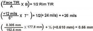
Figure 3.33 Rear feet calculation. The rear feet are 74.0 mils (1.88 mm) too high; shims need to be removed.

Rim-Face Calculation Precautions

  1. Ensure that the rim and face dial indicator TIR’s are properly determined from the dials prior to performing calculations.
  2. Be careful NOT to make mathematical errors when subtracting signed numbers.
  3. Observe parentheses in the equations. Perform operations inside parenthesis first.
  4. Do NOT make human errors substituting real values into the equations.
  5. Ensure that the A, B, and C dimensions are accurate and are properly entered into the equations.

Rim-Face Graph

As discussed earlier, one way to determine the position of the movable machine’s front and rear feet from DIR and DIF TIR values is to perform Rim-Face calculations. Another way is to construct a scaled graph. A main advantage of graphing methods is that the shaft centerlines and misalignment conditions are represented visually.

The information presented here applies to a Rim-Face dial setup where both dial indicators are attached at the same location around the circumference.

Graphing procedures may be applied to both the vertical and horizontal planes of misalignment. However, they are typically applied primarily to the vertical plane. As presented earlier, misalignment in the horizontal plane may be accomplished without calculating or graphing the exact front and rear feet positions.

Setting Up the Graph

To construct a scaled Rim-Face graph, perform the following steps:

  1. Obtain graph paper with 10 divisions between bold lines.
  2. Turn the graph paper so that the long side is horizontal.
  3. Draw a horizontal line at the center of the page.
    1. This line represents the stationary shaft center and is drawn across the page midway down the graph dividing the page. It is helpful if this line is on top of one of the bold lines.
  4. Determine the horizontal plotting scale.
    1. Always use the largest scale possible. Measure the distance from the stationary indicator plunger to the centerline of the rear feet of the movable machine. Standard graph paper is about 260 mm across. The largest horizontal scale will be the machine distance divided by the page width. Note your horizontal scale.
  5. Make a vertical line on the extreme left of the horizontal line.
    1. This mark represents the point where the rim dial indicator contacts the shaft or coupling hub and is labeled: DIR.
  6. Make a second vertical line representing the point along the shaft length of the front feet of the movable machine (FF).
  7. Make a third vertical line representing the point along the shaft length of the rear feet of the movable machine (RF).

Upon completion of the steps above, the graph will look similar to the one shown below. For this example, the B and C dimensions both equal 10 inches.

Figure 3.34 Setting up the graph.

Plotting Offsets

After setting up the graph, the next step is to plot two offset points. One is the offset measured in the plane of the rim dial indicator (DIR). The other offset point is derived from the face dial indicator (DIF) reading and the “A” dimension. To plot the offsets, perform the following steps:

1. Determine the vertical scale.

  • The vertical scale is typically 1 hundred of a mm (0.01) per division. In cases of gross misalignment where the offsets will not fit on the page, a larger scale, such as 2-3 hundreds per division, is sometimes required.

2. Plot the offset from the rim dial indicator on line DIR.

  • Use the horizontal line representing the stationary shaft centerline as the reference. All points above this horizontal line are positive (+) and all points below the line are negative (-).
  • Ensure you divide the Rim Dial TIR by 2 to obtain an offset value.

3. Plot the second offset point using the shaft slope (Face TIR / “A” dimension).

  • Plot this point counting from the DIR offset point!

In the example below, the DIR offset is –0.15 mm and the shaft slope is +0.11 mm over an A dimension of 120 mm.

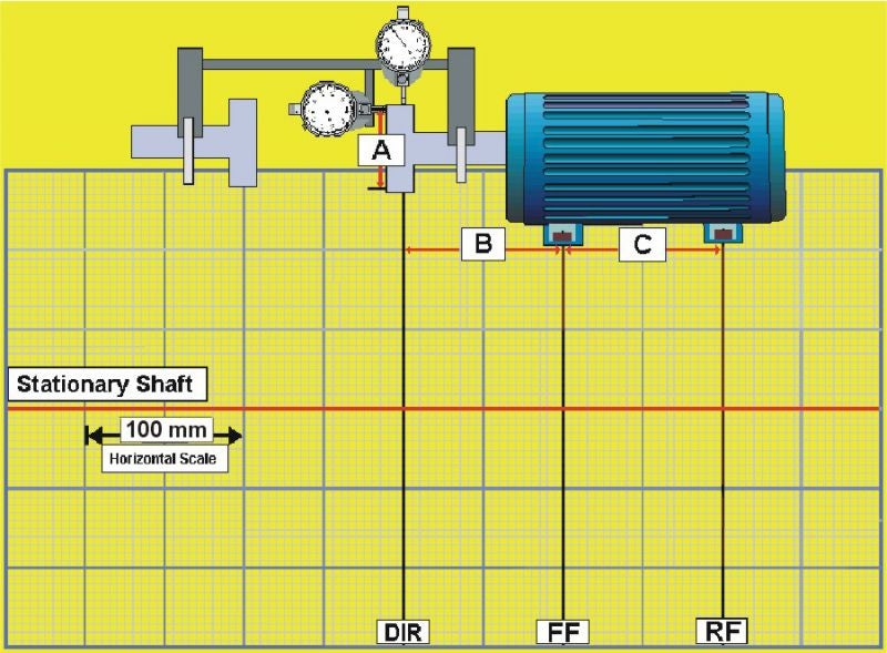
Figure 3.35 Plotting

Determining Movable Shaft Position

After plotting the two points, to determine the movable shaft position perform the following steps:

  1. Using a ruler or straightedge, draw a line through the two offset points that extends to the rear feet of the movable machine.
  2. Count the number of squares in the plane of the front and rear feet to determine the position and corrections needed.

In the example below, the front feet of the machine are 0.06 mm low; shims need to be added. The rear feet are positioned 0.03 too high; shims need to be removed from both rear feet.

Figure 3.36 Graph, feet positions.

Rim-Face Graphing Precautions

  1. Ensure that proper horizontal and vertical scaling techniques are consistently used.
  2. Always double check the position of vertical lines drawn to represent the DIR, FF, and RF.
  3. Ensure that the two plot points are properly determined from TIR’s.
  4. Ensure that positive offsets are plotted above the horizontal reference line and negative offsets are plotted below the line.
  5. When interpreting the graph to determine the movable shaft’s front and rear feet positions in the vertical plane, observe the following rules:
    1. If the movable shaft is above the horizontal stationary shaft reference line, the shaft is too high.
    2. If the movable shaft is below the horizontal stationary shaft reference line, the shaft is too low.
  6. When interpreting the graph to determine the movable shaft’s front and rear feet positions in the horizontal plane, view the graph the way you view the machine, that is, standing behind the movable machine facing the stationary machine. Also, observe the following rules:
  • If the movable shaft is above the horizontal stationary shaft reference line, the shaft is positioned to the right.
  • If the movable shaft is below the horizontal stationary shaft reference line, the shaft is positioned to the left.

Correction Process Overview

To correct misalignment involves a number of different procedures. The sequence of steps in a correction process varies slightly according to the specific alignment conditions of the machine.

Before Correcting Misalignment

Before correcting misalignment , the following procedures are to be performed:

  • Perform pre-alignment checks and corrections.
  • Setup the Rim-Face fixtures.
  • Correct soft foot.
  • Measure misalignment.
  • Determine alignment tolerances.
  • Compare alignment conditions to specified tolerances.

After Correcting Misalignment

After correcting misalignment, the following procedures are to be performed.

  • Re-measure alignment conditions.
  • Compare alignment conditions to specified tolerances.
  • Document final result.

Common Correction Questions

When it comes to actually moving the machine, that is, SOLVING the PROBLEM, several questions are often asked:

  • Do I start with the vertical or horizontal?
  • What about use of precut shims?
  • Should I take a new set of readings after moving vertically or horizontally?
  • Do I need to use dial indicators to monitor the horizontal moves?
  • Is it necessary to use torquing procedures?
  • Do I move the front feet or the rear feet first?

Each of these questions is valid and will be answered in this lesson.

Determining the Sequence of Corrections

Correcting misalignment involves initial and final corrections. Initial corrections are made to minimize the amounts of misalignment and improve the accuracy of alignment measurements.

Prior to making any moves, look at the horizontal and vertical positions of the movable machine. In general, you will start the correction process by making initial corrections in the plane where the misalignment is worse and then make final corrections.

Making Corrections

If

Then

Both Vertical and Horizontal Front and Rear Feet Misalignment is 0.5 mm or less
  • Make final vertical corrections.
  • Make final horizontal corrections.
Both Vertical and Horizontal Front and Rear Feet Misalignment is greater than 0.5 mm
  • Make initial vertical and horizontal corrections.
  • Make final vertical corrections.
  • Make final horizontal corrections.
Either Vertical or Horizontal Front and Rear Feet Misalignment is greater than 0.5 mm
  • Make initial vertical or horizontal corrections.
  • Make final vertical corrections.
  • Make final horizontal corrections.

Consider the following sets of data

Front Feet Vertical Position: +0.2 mm

Rear Feet Vertical Position: +0.5 mm

Front Feet Horizontal Position: -0.4 mm

Rear Feet Horizontal Position: -0.9 mm

In this example, the horizontal misalignment is over twice the vertical misalignment. Therefore, an initial horizontal adjustment will be made; then, final vertical and horizontal corrections will be made.


Making Vertical Corrections

Determine the vertical position of the movable machine using calculation and/or graphing techniques.

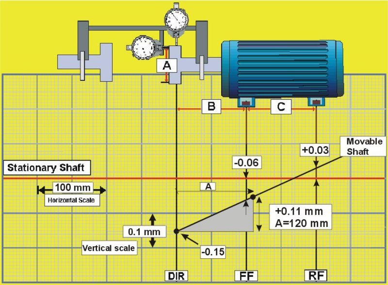
Figure 3.37 Making vertical corrections
  • Positive values at the feet mean that the movable machine is high, therefore you will remove shims.
  • Negative values mean that the movable machine is low, so you will add shims.

Vertical Correction Tips

  1. Make shim changes to both front feet and both rear feet as needed.
  2. Always check shim thickness with an outside micrometer. Precut shims aren’t always what they’re marked; many shim manufacturers designate shims with the “nominal” thickness.
  3. Use consistent and correct torquing procedures.
  4. As shim changes are made, check for and take precautions to avoid creating soft foot conditions.

Horizontal Corrections Process

When using the Rim-Face method, two different procedures are commonly used for horizontal corrections:

  • Determining the corrections using calculation or graphing techniques and monitoring movement using dial indicators positioned at the machine feet.
  • Monitoring movement using dial indicators mounted at the coupling.

To correct horizontal misalignment by monitoring movement at the movable machine feet, perform the following steps:

  1. Measure horizontal misalignment using procedures given in 3.2.4.
  2. Determine the horizontal position of the movable machine using calculation or graphing procedures given in 3.2.5 and 3.2.6.
    1. Ensure that you are standing with the movable machine on your right and the stationary machine on your left.
    2. Positive values at the feet mean that the movable machine is away from you; therefore it should be moved towards you.
  3. Negative values at the feet mean that the movable machine is towards you; therefore it should be moved away from you.
  4. Position dial indicators at the front and rear feet.
Figure 3.38 Horizontal corrections. Dial indicator at the feet.

Move front and rear feet the amounts needed while watching the dial indicators.

To correct horizontal misalignment by monitoring using dial indicators mounted at the coupling, perform the following steps:

  1. Rotate the dial indicators to 9:00 and zero them.
  2. Rotate shafts to 3:00.
  3. Adjust the dial indicators to one-half their values.
  4. Move the front feet of the movable machine as you watch the rim dial indicator move to zero.
  5. Move the rear feet of the movable machine as you watch the face dial indicator move to zero.
  6. Repeat steps 4 & 5 until both dial indicators read zero.
Figure 3.39 Horizontal corrections. Monitoring dial indicators mounted at the coupling.

Horizontal Correction Tips

  1. Start making moves at the feet where the misalignment is greatest.
  2. If not already present, install jackbolts wherever possible.
  3. Bring the front and rear feet into alignment together; they’re a team.
  4. When the feet are within 0.05 mm or so, start torquing and watch the dial indicators. Use the proper criss-cross torquing sequence.

After Making Vertical and Horizontal Corrections

After making final vertical and horizontal corrections, you should:

  1. Obtain new measurements.
  2. Compare results to specified tolerances.
  3. Repeat corrections until results are within tolerances.
  4. Obtain and document a final set of measurements.
  5. Restore equipment in accordance with procedures at your facility.
!
by Acoem contributor | June 13, 2022
Share :

View our resources

Visit our library of educational videos, podcasts and more.

View more

Suscribe to the blog

Ici formulaire à venir

Would you like to…?