Figure 3.71 Coning principle 1. The center of the circle is the rotational center of the shaft.
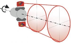
Figure 3.72 Coning principle 2. The axis of rotation is made into a single point at a distance from the shaft end.
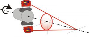
Figure 3.73 Reverse-Rim dial indicator method. Measurement of stationary side offset, DIS.
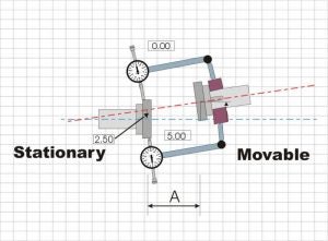
Figure 3.74 Twin laser method. Measurement of stationary side offset, TD-S
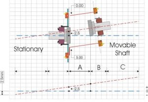
Figure 3.75 Reverse-Rim method. Measurement of movable side offset, DIM
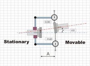
Figure 3.76 Twin laser method. Measurement of movable side offset, TD-M.
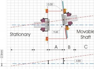
(real time)Figure 3.77 Equations

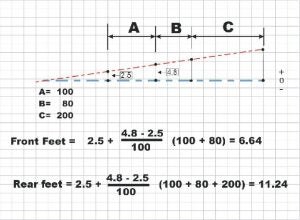
Figure 3.78 Example, feet calculation.
