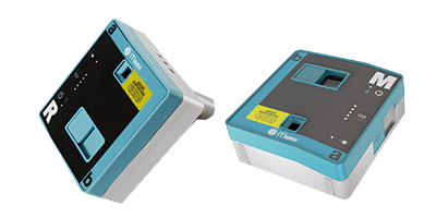
MT30

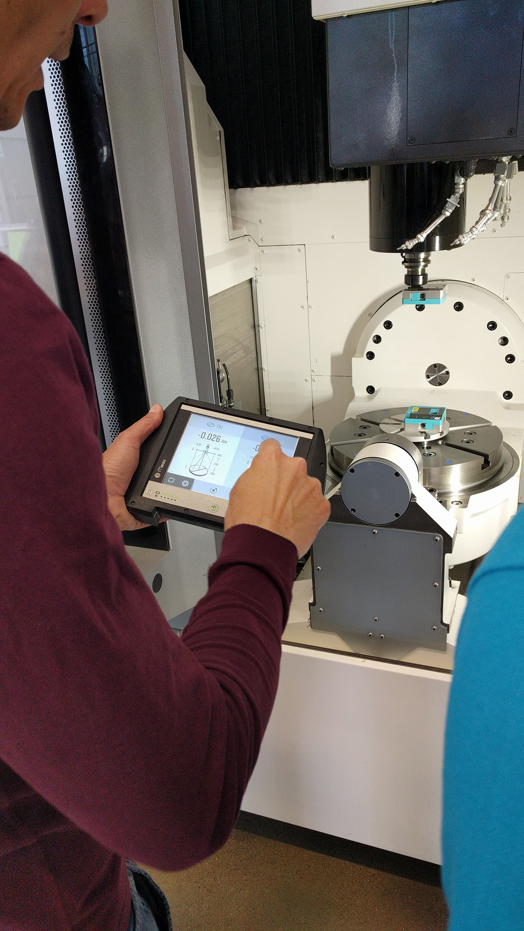
Machine Tool Calibration

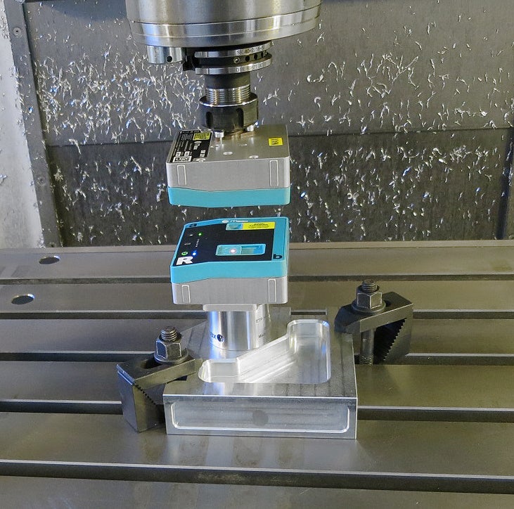
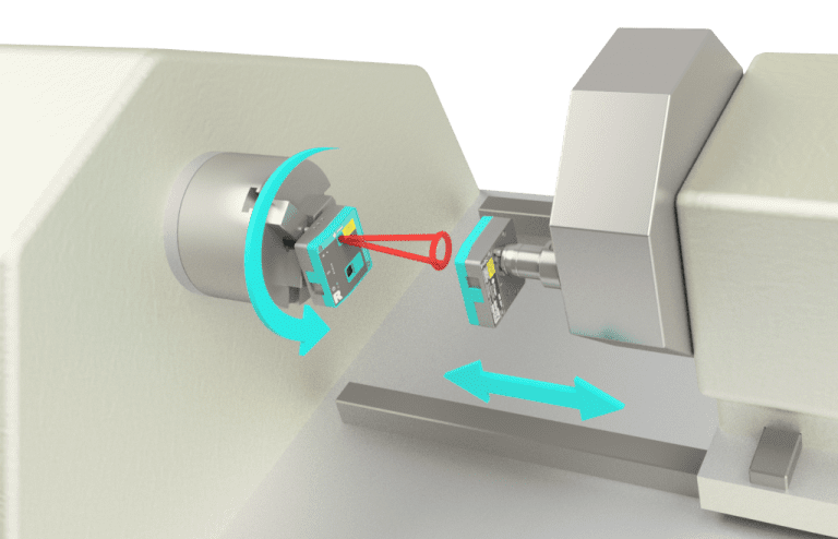
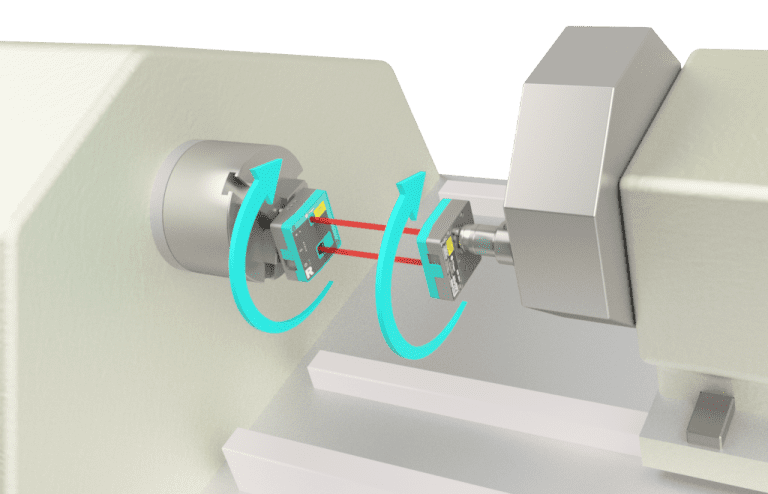
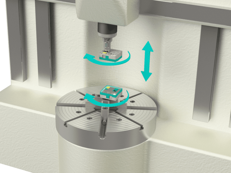
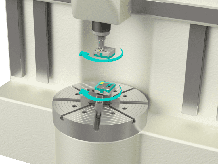
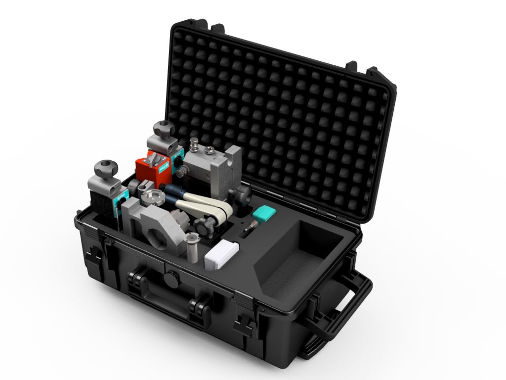
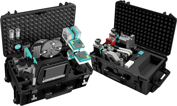
MT30 is a complete product package for checks in both lathes, milling machines as well as turning and machine center.

Features

STREVEL™
To check that the machine’s movements run straight without any pitch and roll, a solution with multiple sensors is required
Measuring spindle alignment
Because deviations in spindle alignment impact on the machined part, it is important that this can be easily measured
Measuring and adjusting the tool holder
Using the SR and SM sensors, you can measure alignment between the main spindle and the tool holder to quickly set a zero point in the tool holder
Measuring Squareness
By fitting a prism to SR, you can measure whether the machine’s movements are square with each other
Vertical Spindle Alignment
Used to determine the direction of rotational axis of a machine spindle in relation to a vertical machine movement
Vertical Coaxiality
Used to determine the direction of rotational axis of a machine spindle in relation to a main spindle
Spindle Parallelism
Used to determine the direction of rotational axis of a machine spindle relative to its own horizontal movement
Vertical Spindle Parallelism
Used to determine the direction of rotation of a spindle axis relative to its own vertical movement

See our technology in action.

Schedule a free demo to get a first-hand look at how our solutions support your business.

A solution with multiple sensors!

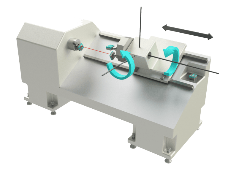
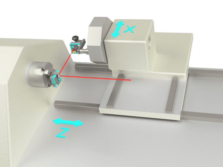
Checks the straightness of the machine’s movement, at the same time as measuring the angular deviation of the movement in relation to the machine bed!

How works the MT30

Contains five measuring sensors that are all connected wirelessly to the display unit in which all measurement results are calculated and presented immediately to the user. The results of the measurements are presented both graphically and numerically for a simple assessment and can be stored in the memory on the display unit.

A measurement report with all measurements in a machine can be created in PDF format directly in the display unit, or the results can be exported using a USB stick for further documentation.

The measuring sensors in the Acoem system are precision instruments specially designed to provide high accuracy in a challenging measurement environment. MT30 comes in two robust trolley cases that make it convenient to transport and carry the entire system.

Hardware DU – Display unit

DU is a robust display unit that has been specifically designed for use in a workshop environment where there are high demands on reliability and resistance to both cutting fluids and dirt.

The display box has a strong aluminium frame and a rubber coated surface that makes it extremely shock resistant while rendering it easy to hold and means it can be put down on the machines without it sliding away.

A large, clear 6.5” colour touch screen that makes it easy for users to see and provides the option of viewing what is displayed on screen even at a long distance. All this to allow for a flexible use of the system even in a tough environment.

SM / SR – Measuring sensors

SR201 and SM201 serve as multifunctional sensors.
They both have an integrated laser transmitter, a 2-axis PSD detector and a high-resolution inclinometer to record the angle of rotation. The sensors are used for a variety of types of measurements such as straightness, squareness, spindle direction, and coaxiality. The SR unit (marked R) is fitted to the part of the machine which forms a reference, and the SM sensor (marked M) is fitted to the machine axis that is to be measured.

LM / LR – Angle sensors

MT30 contains two twin axis measuring sensors for accurate angular measurement. Acoem angle sensors have a unique design with wireless communication via Bluetooth and a rechargeable battery. It allows use of the machine even if the machine doors are closed, which is a prerequisite for working safely in the machine. Wireless communication also allows the option for the operator to bring the display unit to the location where the alignment is to be made when setting up the machine.

PEN

Pen is a battery-powered measuring pen that connects wirelessly via Bluetooth to the display unit or to a mobile device using an App. The measuring sensor can be used for operations like the measurement of machine spindles, movements/gaps in machine slides, measurement of repetition accuracy in fixtures or turning gaps in machine movements. The wireless transmission enables the sensor to be mounted in the machine where you can perform the measurements with the machine doors closed.

SQ201 – Angle prism

When measuring squareness, use the SQ201 angle prism that is fitted to the SR sensor and angles the output laser beam at 90° with an accuracy within 0.005 mm/m. The angle prism has a built-in mechanical device that allows you to alter the direction of the laser beam at any time during the measurement process with a simple manual operation. As the SQ201 has small installation dimensions, this means that it can be installed in machines where there are short distances and where you want to maximise the distances between the measurement points. Its light weight minimises the risk of sag.

Software STREVEL™ measuring Straightness and Level

To check that the machine’s movements run straight without any pitch and roll, a solution with multiple sensors is required.

The LR sensor is positioned on the machine bed and the LM sensor is fitted to the tool holder using the attachment supplied. The SR sensor is mounted in the main spindle and the
SM sensor in the tool holder. The result is displayed as a set of measured points along the length of the movement.

In this way MT30 checks the straightness of the machine’s movement, at the same time as measuring the angular deviation of the movement in relation to the machine bed. The result is displayed in both graphic and text form, and can easily be exported via USB.

Measuring Spindle Direction

Because deviations in spindle direction impact on the machined part, it is important that this can be easily measured. You check the deviation via four measured points in two positions along the Z axis. By rotating the laser in the spindle and moving the SM sensor along the Z axis, you obtain result for parallel alignment between the rotational axis of the spindle to the 2-axis movement. The results are displayed in graphic form in two directions: at square and parallel to the machine bed and in parallel with it.

Measuring Coaxiality

Using the SR and SM sensors, you can measure alignment between the main spindle and the tool holder to quickly set a zero point in the tool holder.

The measuring instrument guides you through the entire measuring process. The software shows you how to take measurements in four rotation positions and then calculates a result that shows the angular error and centre deviation between spindle and tool holder. Adjustments can then be made in the live function unique to Acoem.

Measuring squareness

By fitting a prism to SR, you can measure whether the machine’s movements are square with each other. The measurement is performed in two steps: first by measuring the X axis and then the Z axis.

The software helps you perform the measurement; you will see the angle deviation directly. The customized fixture makes it easy to fit the sensors, thus ensuring a correct result of the machine squareness.

Measuring Vertical Spindle Direction

Used to determine the direction of rotational axis of a machine spindle in relation to a vertical machine movement. In this type of measurement, the machine movement is used as a reference line. The measurement is performed by mounting the SR sensor in the spindle and with the SM sensor mounted in the machine movement.

When measuring, the spindle is rotated 180 degrees while the machine slide with the SM sensor is moved in two positions. The results are presented as a deviation angle in relation to the reference line in two directions.

Measuring Vertical Coaxiality

Used to determine the direction of rotational axis of a machine spindle in relation to a main spindle. The main spindle’s rotational axis is used as a reference and the rotational axis of the other objects are measured in relation to this.

The results are presented as an angle and an offset in two directions: square to the machine bed and parallel to it.

Measuring Spindle Parallelism

Used to determine the direction of rotational axis of a machine spindle in relation to a main spindle. The main spindle’s rotational axis is used as a reference and the rotational axis of the other objects are measured in relation to this. The results are presented as an angle and an offset in two directions: square to the machine bed and parallel to it.

Measuring Vertical Spindle Parallelism

Used to determine the direction of rotation of a spindle axis relative to its own vertical movement. The SM unit is mounted in the machine spindle and the SR¬unit is mounted in the opposing spindle (or in the indexing fixture). By rotating the SR-sensor 180 degrees and moving the machine axis in two positions and then taking a coaxiality measurement, the parallelism between the spindle and the machine movement can then be calculated.

Pointing fixture

Used for measuring squareness in vertical and horizontal mills and multi-operation machines. The fixture can be attached directly to the machine table, where the pointing direction can be set vertically or horizontally.
Alternatively, the fixture can be mounted in the machine spindle depending on the machine configuration that applies to the measurement.

The SR-sensor with angular prism is mounted in the fixture and the direction of the laser can be adjusted parallel to one of the machine movements with the aid of the built-in micrometer screws. The rotation angle of the SR sensor is then calibrated to ensure that the angled laser beam is aligned with the other machine axis.

Indexing fixture

This fixture is used to measure parallelism between a rotating spindle and its own movement when the spindle is mounted on a machine axis. The fixture can be mounted in a variety of ways to be able to measure in machines with horizontal and/or vertical movements. The fixture consists of a hydraulic clamping chuck with four indexing positions, an attachment to the SM sensor and a mounting plate for fitting to the machine table. The hydraulic chuck can also be mounted on the circular mounting plate or shaft extension with diam. 20 and 16 mm.

Magnetic sensor stand

The magnetic stand is used when the SM sensor can not be mounted in a machine spindle, tool mount or with any of the accompanying magnetic feet. The measuring stand has a flexible 3-conductor arm that can be locked sequentially with a lock handle. The SM-sensor with shaft extension is mounted in the stand using a clamp bracket that allows you to adjust the rotational angle of the sensor, for example, parallel to the machine bed.

Circular mounting plate

Used for the installation of SR or SM sensor in spindles without chucks, or directly on the spindle nose. Can also be used with a hydraulic clamping chuck from the indexing fixture.
Comes with magnets and extension rods (L=40 mm, L=80 mm)

The future of machine measurement

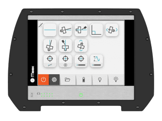
As ever-increasing demands are being placed on machine tools, we have arrived at the conclusion that an optimally functional machine forms the basis for better business. Modern machine tools must maintain a high level of flexibility, a high degree of utilization and a minimum downtime which calls for the correct geometry in all the machine’s movements. So we created Acoem and started to sketch solutions for machine tool measurements that, in our opinion, are so self-evident that they should have been developed a long time ago. By performing fast measurements, possessing a logical user interface, smart applications and fewer complicated functions, we can now build a future for machine tool measurement.

Request pricing

Connect with Acoem

Contact us to learn more about our solutions, services, and training programs.

Would you like to…?